Controlling Inkjet Printers from a microcontroller

There was an interesting thread on the Sketching in Hardware mailing list a while back on how to control an inkjet printer.   Wendy Ju started the discussion. Following are some of the links from that thread:

A closed, proprietary portable printer:  Xyron Design Runner

Nice explanation of how inkjets work and how to control them in general. Link submitted by Scott Minneman

Instructions for now sold-out Parallax Serial Inkjet Kit (which does include inkjet cartridge pinouts for the HP 51604A Black Inkjet Cartridge, as well as board schematics, parts and instruction routines for  writing to the cartridge). Even without the device, Parallax’ documentation is handy.

Instructions on how to build your own DNA microarrayer using commercial off-the-shelf parts, including inkjet technologies.  The last two links submitted by Wendy.

Haven’t had occasion to use these yet, but they seem handy.

DC Motor Control with a TIP120 Transistor

This example assumes you’re using a DC motor that runs on low voltage DC, in the 5-15V range. Connect leads to its terminals, and run if from a benchtop power supply if you have one. Try changing the voltage on it, and seeing what effect it has. Don’t go over the motor’s rated voltage. Connect a switch in series with the motor and use it to turn on the motor.

Continue reading “DC Motor Control with a TIP120 Transistor”

Random Numbers and Physical Computing

Most microcontrollers don’t have a random function. Random functions are not truly random, they’re actually a complex mathematical formula that results in a number that “seems” random. That can take up lots of processing time, so it’s usually the first function to go when writing a microprocessor language.

In fact, most of what you do in programming physical computing projects is to figure out how to deal with the world’s natural randomness and make it look smooth. A photoresistor read through an analog-to-digital converter, for example, will never give you a nice steady number, it always fluctuates with tiny changes in lighting that your eye can’t see. Your consciousness is a great leveller for the sensors that are your eyes, ears, skin, nose, and taste buds When you move a photoresistor from one room to another, your readings will be totally different, and all of a sudden, you have to re-calculate what is “average” and what constitutes the lighting change that you want. And that’s just one of many examples. The fact is, data from sensors is filled with the noise of the real world. Plan for it in advance.

Technorati Tags: , ,


Continue reading “Random Numbers and Physical Computing”

Sound in to a Microntroller

Microcontrollers can take sound in as an analog input, for crude measurements. While 8-bit ones  (the Basic Stamp, BX-24, PIC, Arduino, etc) are not fast enough to read the frequency difference between various sounds, they can read sound levels. A line-level audio signal (which is what a typical CD or MP3 player produces) varies between -1V and 1V, a range of 2V total. If you raise that up so that it varies between, say, 3.5V and 1.5V, you can read it using the analog input on your microcontroller

First, if you have a microphone, you won’t be able to connect it directly. A microphone’s voltage, known as mic level voltage, is only a few millivolts at best. If you put it through a preamp such as a mixer board, or through an amplifier, you get a line level signal, which you can read.

A simple way to do this is to buy a preamplifier kit, something like the Velleman K1803 Universal Mono Preamplifier from Jameco (part no. 117612). For $8.95, it’ll save you some troubleshooting time, and cost about as much as the circuit below. Or you can build your own.

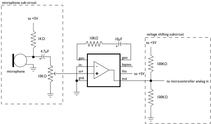
The following circuit uses a Condenser microphone element from Radio Shack (part no. 270-090C) and an amplifier chip also from Radio Shack (LM386 Audio Amplifier). The amplifier raises the microphone’s signal so it’s within line level tolerances, -1V to 1V. To raise that to a 1.5V to 3.5V range, we use a voltage divider (the two 100K resistors). Normally, the voltage between the resistors would be 2.5V (since their resistance is equal). When we add in the line level signal, we get 1.5V to 3.5V.

Note that the 10K variable pot is using all three pins of the potentiometer. The center pin goes to pin 2 of the amplifier, the end pins to the mic and pin 3, respectively. The variable resistor is your volume knob. I used an audio taper pot, since I wanted the curve of the pot to follow the sound’s volume.

Note that the capacitors are polarized electrolytic capacitors, so it matters which way they face.

In the BX-BASIC code, I found my base value (when all was silent) was about 512. So I subtracted that, took the absolute value of the result (so that negative numbers would always read as positive), and got a sound level varying between about 1 and 500. You may need to adjust these values depending on your setup.

dim soundIn as integer

Sub main()
    call delay(0.5)  ' start  program with a half-second delay 

    do
        soundIn = abs(getADC(13)- 512)

        debug.print "soundIn = " ; cStr(soundIn)
    loop

End Sub

Here’s the same code in Wiring/Arduino:

void setup() {
	Serial.begin(9600);
}

void loop() {
	// read the audio in on analog 0:
	int soundLevel = analogRead(0) -512;
       Serial.print( "soundIn = ");
	Serial.println(soundLevel, DEC);
}