This example shows how to control 64 LEDs and read the input from two axes of an accelerometer on an Arduino. The Arduino used here is a Duemilanove, but it will work on any of the models out there prior to the Duemilanove as well. This example uses row-column scanning as a way to control more LEDs than you have output pins. It also uses some of the analog pins as digital I/O pins.
Parts you’ll need
- Arduino Duemilanove or equivalent
- 2-axis accelerometer. I used the ADXL335 breakout board from adafruit.com, and only used two axes.
- 8×8 LED matrix. I used one I bought surplus. See this post for details on figuring out your matrix’s pins if you don’t have the data sheet.
- Breadboard or prototyping shield. I used the proto shield and tiny breadboard from adafruit.com.
The circuit
Connecting the matrix
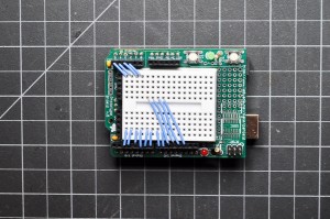
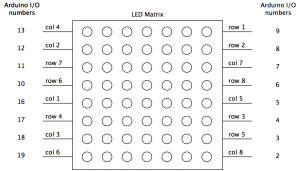
Since all of the pins of the matrix are going to be connected to digital I/O pins of the Arduino, it doesn’t matter what order you connect them in. You can arrange them as you need them in software. So connect them in a way that makes the wiring simple. I left digital pins 0 and 1 free since they’re the serial communication pins. You’ll need to use four of the analog inputs as digital I/O pins to get 16 pins. When used as digital I/O, the analog pins 0 through 5 are digital I/O pins 14 through 19, respectively. I used pins 2 through 13, and 16 through 19. Here’s how it looks:
|
|
Connecting the Accelerometer
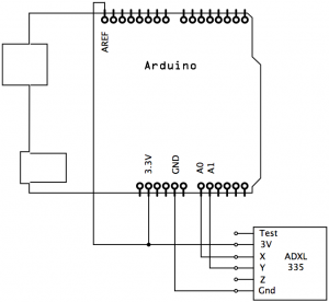
The accelerometer runs on 3.3V. If you’re using an Arduino that doesn’t have a 3.3V output (i.e. any prior to the Diecimila), you’ll need to add a 3.3V voltage regulator. Otherwise, you can connect directly to the 3.3V output of the Arduino. Connect the accelerometer’s 3V pin to the Arduino’s 3.3V output, and the ground to the Arduino’s ground. Connect the accelerometer’s X and Y axes to analog inputs 0 and 1, respectively. Make a connection from the 3.3V pin to the Arduino’s AREF too, so that the analog inputs know that the maximum voltage that the accelerometer will output is 3.3V. Here’s what the wiring looks like:
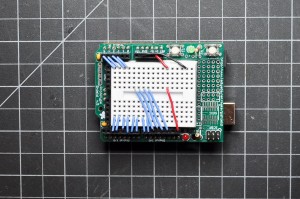
The final assembly looks like this:
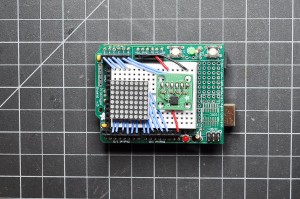
Now that the board is assembled, you’re ready to write some code.
The Code
You’ll code this in three parts: First, a quick sketch to test and scale the accelerometer. Then, a second sketch to test the matrix. Finally, a sketch to combine them.
Test the Accelerometer
You need to know the range that the accelerometer outputs. To do this, enter the following code:
void setup() {
  // initialize the serial port:
  Serial.begin(9600);
}

void loop() {
  // print the analog readings, separated by a tab:
  Serial.print(analogRead(0));
  Serial.print("t");
  Serial.println(analogRead(1));
}
Next, with the serial monitor open, tilt the board 180 degrees in the X or Y axis. Write down the maximum and minimum values you get. Then repeat for the other axis. Your range will vary, but you should get values ranging from about 380 to 620. Note these values. They will be the maxima and minima for mapping the accelerometer values to pixel movement later.
Test the Matrix
To control the matrix, first you need to have your I/O pins arranged sensibly. Since they’re in a non-numerical order, the easiest way to manage them is to put them into two arrays that you can iterate over. Arrange the pins in the array so that the pin number for row 1 corresponds with array element row[0], row 1 with row[2], and so forth, like so:
const int row[8] = {
  9,8,4,17,3,10,11,6  };

const int col[8] = {
  16,12,18,13,5,19,7,2  };
Once you’ve got them in arrays, you can set up for loops to work with the pins easily. Here’s a setup method to initialize all the pins, and to take the cathodes high so all the LEDs are off:
void setup() {
  // initialize the I/O pins as outputs:

  // iterate over the pins:
  for (int thisPin = 0; thisPin < 8; thisPin++) {
    // initialize the output pins:
    pinMode(col[thisPin], OUTPUT);
    pinMode(row[thisPin], OUTPUT);
    // take the col pins (i.e. the cathodes) high to ensure that
    // the LEDS are off:
    digitalWrite(col[thisPin], HIGH);
  }
}
In the matrix I used, the rows were the anodes and the columns were the cathodes. It may be the reverse for your matrix. If so, reverse them in the code. Take the cathodes high to ensure that the LEDs are off, whether they are the rows or columns.
In the main loop, you use two nested for loops. The outer loop takes the anodes high one at a time, then the inner loop iterates over the cathodes. To turn a given LED on, take its cathode low; to turn it off, take its cathode high.
Again, if your rows and columns are reversed from this, you need to correct the code. The anodes are always taken high in the outer for loop, and the cathodes in the inner loop.
void loop() {
  // iterate over the rows (anodes):
  for (int thisRow = 0; thisRow < 8; thisRow++) {
    // take the row pin (anode) high:
    digitalWrite(row[thisRow], HIGH);
    // iterate over the cols (cathodes):
    for (int thisCol = 0; thisCol < 8; thisCol++) {

      // when the row is HIGH and the col is LOW,
      // the LED where they meet turns on:
      digitalWrite(col[thisCol], LOW);
      // wait a few milliseconds to see it:
      delay(30);
      // turn the pixel off:
      digitalWrite(col[thisCol], HIGH);
    }
    // take the row pin low to turn off the whole row:
    digitalWrite(row[thisRow], LOW);
  }
}
Here’s a simpler loop method that just turns on all the LEDs:
void loop() {
  // iterate over the rows (anodes):
  for (int thisRow = 0; thisRow < 8; thisRow++) {
    // take the row pin (anode) high:
    digitalWrite(row[thisRow], HIGH);
    // iterate over the cols (cathodes):
    for (int thisCol = 0; thisCol < 8; thisCol++) {
      // when the row is HIGH and the col is LOW,
      // the LED where they meet turns on:
      digitalWrite(col[thisCol], LOW);
    }
  }
}
Once you know all the LEDs work you can put the whole thing together.
Combine the Input and Output
The following sketch reads the accelerometer values from the X and Y axes, and maps them to a 0 to 7 range. Then it sets the position of a pixel in a two-dimensional array to the scaled X and Y values. Finally, it reads the matrix to light the LEDs of the matrix.
The global variables are a bit more extensive. In addition to the arrays, you now need a two-dimensional array for the pixel array, and two ints for the X and Y position. You also need to constants for the sensor minima and maxima:
// max and min values from the accelerometer,
// found by experiment:
const int sensorMin = 380;
const int sensorMax = 620;

// 2-dimensional array of row pin numbers (for two matrices):
const int row[8] = {
  9,8,4,17,3,10,11,6  };

// 2-dimensional array of column pin numbers (for two matrices):
const int col[8] = {
  16,12,18,13,5,19,7,2  };

// 2-dimensional array of pixels:
int pixels[8][8];

// cursor position:
int x = 5;
int y = 5;
The setup is basically the same as above, but adds a for loop to initialize the 2D pixel array. The pixel array is holding the values of the cathode for each LED, so you set each element HIGH so they’re all turned off:
void setup() {
  Serial.begin(9600);
  // initialize the I/O pins as outputs:

  // iterate over the pins:
  for (int thisPin = 0; thisPin < 8; thisPin++) {
    // initialize the output pins:
    pinMode(col[thisPin], OUTPUT);
    pinMode(row[thisPin], OUTPUT);
    // take the col pins (i.e. the cathodes) high to ensure that
    // the LEDS are off:
    digitalWrite(col[thisPin], HIGH);
  }

  // initialize the pixel matrix:
  for (int x = 0; x < 8; x++) {
    for (int y = 0; y < 8; y++) {
      pixels[x][y] = HIGH;
    }
  }
}
The loop is very simple, to let you know what’s happening. All the work is done in external methods:
void loop() {
  // read input:
  readSensors();

  // draw the screen:
  refreshScreen();
}
The readSensors() method reads the accelerometer and scales the values to the width and height of the pixel array. First, though, it sets the last pixel position HIGH to turn it off. Once it’s read the new value, it sets the corresponding array element LOW so that pixel will turn on:
void readSensors() {
  // turn off the last position:
  pixels[x][y] = HIGH;
  // read the sensors for X and Y values:
  x = 7 - map(analogRead(0), sensorMin, sensorMax, 0, 7);
  y = map(analogRead(1), sensorMin, sensorMax, 0, 7);
  pixels[x][y] = LOW;
}
The refreshScreen method does all the work of controlling the pixels. It looks a lot like the nested for loops above. The biggest change is that it gets its value for each cathode from the 2D pixel array:
void refreshScreen() {
  // iterate over the rows (anodes):
  for (int thisRow = 0; thisRow < 8; thisRow++) {
    // take the row pin (anode) high:
    digitalWrite(row[thisRow], HIGH);
    // iterate over the cols (cathodes):
    for (int thisCol = 0; thisCol < 8; thisCol++) {
      // get the state of the current pixel;
      int thisPixel = pixels[thisRow][thisCol];
      // when the row is HIGH and the col is LOW,
      // the LED where they meet turns on:
      digitalWrite(col[thisCol], thisPixel);
      // turn the pixel off:
      if (thisPixel == LOW) {
        digitalWrite(col[thisCol], HIGH);
      }

    }
    // take the row pin low to turn off the whole row:
    digitalWrite(row[thisRow], LOW);
  }
}
This same method can be used for more complex animations; in fact, it’s the most common way of managing computer animation. You store the image in an offscreen array, then rely on a driver method to read the array and set the appropriate elements.
That’s the whole sketch. When you run it, you should see an initial state like this, when your board is sitting on a level surface:
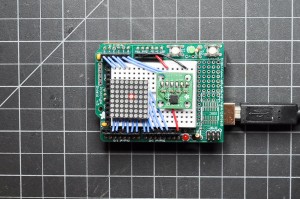
You can use this same method for controlling other outputs as well. You’ll need to replace the LEDs with NPN transistors. Put the base of the transistor in place of the LED and connect the load to the transistor the same way you normally would for a high current load. Now you can control a whole lot more physical output. Enjoy!
Here’s the final sketch for download.
One Reply to “Tilty ball: Controlling 64 LEDs and a 2-axis accelerometer”
Comments are closed.