These notes are heavily indebted to Gordon McComb’s Robot Builder’s Bonanza, second edition, which includes some excellent chapters on motors and motor use.
For a good article on controlling motors from a microcontroller, see Driving High-current Loads from Logic.
When trying to move things with microcontrollers, there are basically three kinds of motors that are most useful: DC motors, servomotors, and stepper motors. Following is a brief introduction to these three. More notes can be found all over the web, and in many good electronics and robotics books.
Most all motors work on the electrical principle of induction. When you put electric current through a wire, it generates a magnetic field around the wire. By placing a charged coil of wire in an existing magnetic field (say, between two magnets), the coil will be either attracted to one magnet and repelled by the other, or vice versa, depending on the current flow. The higher the current, the greater the magnetic field, and therefore the greater the attraction or repulsion. The coil is mounted on a spinning shaft in the middle of the motor. As the coil is alternately attracted to one magnet and repulsed by the other, it spins from one to the other, and we get circular motion.
All inductive loads (like motors, electromagnets, and solenoids) work on this same principle: induce a magnetic field by putting current through a wire, use it to attract or repulse a magnetic body. However, the principle works in reverse as well. When you spin a wire in an existing magnetic field, the field induces a current in the wire. So if you’ve got a motor spinning, and you turn it off, the fact that the motor’s coil is spinning in a magnetic field will generate a current in the wire for a brief amount of time. This current comes back in the reverse direction of the current flow you generated to run the motor. It’s called blowback, or back voltage, and it can cause damage to your electronics. Usually it’s stopped by putting a diode in line with your motor, to stop the back voltage.
Motor Characteristics
There are a few characteristics common to all motors that you should keep in mind when looking for motors:
Voltage
The rated voltage of a motor is the voltage at which it operates at peak efficiency. Most DC motors can be operated somewhat above or below their range, but it’s best to plan to operate them at their rated voltage. Dropping below rated voltage reduces the motor’s power, and operating above the rated voltage may burn the motor out. Plan on the motor’s top speed being at rated voltage, and slowest speed at no more than 50% less than the rated voltage.
Current
Motors draw current depending on the load they’re pulling. Usually more load means more current. Every motor has a stall current, which is the current it draws when it’s stopped by an opposing force. This stall current is much greater than the running current, or current that it draws under no load. Your power supply for a motor should be able to handle the stall current with extra amperage to spare. Motors may draw near the stall current for a brief period of time when starting up, to overcome their inertia.
Speed
Motor speed is given in revolutions per minute (RPM’s).
Torque
Torque is the measure of a motor’s pulling force. It’s measured by the force a motor can pull when the opposing force is attached to a shaft attached to its center rod. If the shaft sticks out a foot from the motor’s center, and the motor can pull one pound on that shaft, the motor’s torque is one foot-pound. Motor manufacturers haven’t standardized this measurement, so sometimes you will see it as ft.-lb., lb-ft., oz.-in, in.-oz., g-cm (gram-centimeter), and any other weight to length variation you can think of.
Resistance
Often you’ll see a motor rated in ohms. This just gives you the resistance that the motor’s coil offers. Using Ohm’s Law (voltage = current x resistance), you can calculate the motor’s current draw if you know the rated voltage and the coil resistance.
The DC Motor
The DC Motor is the simplest of the motors discussed here. It works on exactly the principle discussed above. There are two terminals, and when you apply direct current to one terminal and ground the other, the motor spins in one direction. When you apply current to the other terminal and ground the first terminal, the motor spins in the opposite direction. By switching the polarity of the terminals, you reverse the direction of the motor. By varying the current supplied to the motor, you vary the speed of the motor. Specific techniques for doing these tasks are discussed below.
DC motors are usually very fast, spinning at several thousand revolutions per minute (RPM).
The Gearhead Motor
Gearhead motors are a subset of DC motors. They have a box on the top of the motors containing a series of gears that slow the rotational speed of the motor down and increase the torque. They are useful when you don’t need a lot of speed, but you do need power.
The Servo Motor
For a nice short intro to servos, see the Seattle Robotics page.
Servo motors are a variation on the gearhead motor coupled with a potentiometer to give feedback on the motor’s position. The gears of the gearbox on a servo are attached to a potentiometer inside the case, and the pot is turned by the turning of the motor. The pot is connected to a capacitor in a resistor-capacitor circuit (R-C), and by pulsing this R-C circuit, you give the motor power to turn. When the motor turns, it changes the resistance of the R-C circuit, which in turn feeds the motor again. By pulsing the R-C circuit, you set the motor’s position in a range from 0 to 180 degrees.
Servos have three wires to them, unlike most DC and gearhead motors, which have two. The first two in a servo are power and ground, and the third is a digital control line. This third line is used to set the position of a servo. Unlike other DC motors, you do not have to reverse the polarity of a servo’s power connections to reverse its direction.
Hobby servos, the kind most often used in small physical computing projects, usually take a pulse of between 1-2 ms every 18-20 ms. They rotate 0 to 180 degrees depending on the pulsewidth. A pulse of 1 ms will turn the motor to 0 degrees; 2 ms will turn it to 180 degrees. A servo needs to see a pulse every 18-20 ms even when it is not turning, to keep it in its current position, so once you’ve moved the motor to a new position, it’s essential to keep pulsing it with the same pulsewidth to keep it there.
The Stepper Motor
Stepper motors are different than regular DC motors in that they don’t turn continuously, but move in a series of steps. A stepper motor is a motor controlled by a series of electromagnetic coils. The center shaft has a series of magnets mounted on it, and the coils surrounding the shaft are alternately given current or not, creating magnetic fields which repulse or attract the magnets on the shaft, causing the motor to rotate.
This design allows for very precise control of the motor: by proper pulsing, it can be turned in very accurate steps of set degree increments (for example, two-degree increments, half-degree increments, etc.). They are used in printers, disk drives, and other devices where precise positioning of the motor is necessary. Steppers usually move much slower than DC motors, since there is an upper limit to how fast you can step them (5-600 pulses per second, typically. However, unlike DC motors, steppers often provide more torque at lower speeds. They can be very useful for moving a precise distance. Furthermore, stepper motors have very high torque when stopped, since the motor windings are holding the motor in place like a brake.
To control a stepper, it’s necessary to create a stepper driver that will energize the coils in the right order to make the motor move forward.
The first thing to do is to understand the wiring for a stepper motor. The most common type is a unipolar stepper motor, with six wires and four coils (actually two coils divided by center wires on each coil). To do this, take an ohmmeter to the wires and measure the resistance from one wire to another. The outer wires for each coil will have a definite resistance that is double the resistance between the inner wire and either of the two outer wires, as follows in the diagram below:

e.g.: if the resistance between wires 1 and 5 is x Ohms, then that between 1 and 2 is 2x Ohms. Remember, two wires that are not connected (e.g. 1 and 3, 4, or 6) have infinite resistance, which should read as an error on your meter. When you put voltage across two wires of a coil (e.g. 1 to 2, or 3 to 4), you should find that the motor is very difficult to turn (don’t force it, that’s bad for the motor).
Like other motors, the stepper requires more power than a microcontroller can give it, so you’ll need a separate power supply for it. Ideally you’ll know the voltage from the manufacturer, but if not, get a variable DC power supply, apply the minimum voltage (hopefully 1V or so), apply voltage across two wires of a coil (e.g. 1 to 2 or 3 to 4) and slowly raise the voltage until the motor is difficult to turn. It is possible to damage a motor this way, so don’t go too far. Typical voltages for a stepper might be 5V, 9V, 12V, 24V. Higher than 24V is less common, and frankly, above that it’s best not to guess.
To control the stepper, apply voltage to each of the coils in a specific sequence. These phasing sequences differ for different types of steppers, but for a 4-phase unipolar stepper like the one described above, the phasing would go like this:
| Step | wire 1 | wire 2 | wire 3 | wire 4 |
| 1 | High | low | high | low |
| 2 | low | high | high | low |
| 3 | low | high | low | high |
| 4 | high | low | low | high |
Note: wires 5 and 6 are wired to the supply voltage.
Typically, you would drive the stepper by connecting the 4 phase wires to a good power transistor or MOSFET,and the 2 common wires to the supply voltage, as follows:
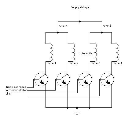
In this diagram, the transistors are TIP120 Darlington transistors. A convenient way to do this is with a ULN2003 or ULN2004 Darlington transistor array from Allegro Micro.
Once you have the motor stepping in one direction, stepping in the other direction is simply a matter of doing the steps in reverse order. Knowing the position is a matter of knowing how many degrees per step, and counting the steps and multiplying by that many degrees. So for examples, if you have a 2-degree stepper, and it’s turned 180 steps, then it’s turned 2 x 180 degrees, or 360 degrees, or one full revolution.
For more on stepper control, see this example.
For a more technical discussion of stepper motor control, see Control Of Stepping Motors, a tutorial, by Douglas W. Jones. Another good tutorial on steppers is at Ian Harries’ site.
One Reply to “Motors”
Comments are closed.