There are two easily controllable parameters of a DC motor, direction and speed. To control the direction, the polarity of the motor is reversed. To control the speed, the input voltage is varied using pulsewidth modulation.
Direction Control
To control a DC motor from a microcontroller, you use switching arrangement known as an H bridge. It looks like this:
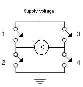
When switches 1 and 4 are closed and 2 and 3 are open, voltage flows from the supply to 1 to the motor to 4 to ground. When 2 and 3 are closed and 1 and 4 are open, polarity is reversed, and voltage flows from the supply to 3 to the motor to 2 to ground.
An H-bridge can be built from transistors, so that a microcontroller can switch the motor, like this:

You can see that there are six transistors here; the outer two are used to switch the inner four, in pairs, so that the proper two transistors always switch together. If you were using this circuit, you’d want to make sure that control pins 1 and 2 were always reversed; when one is high, the other is low.
Although you can make your own H-bridges, it’s usually easier to use a controller manufactured specifically for the job. A pre-manufactured H-bridge chip will include diodes to protect the transistors from back voltage, sometimes a current sensing pin to sense the current the motor is drawing, and much more. There are many motor drivers available from various electronics suppliers. Look around to find one that suits your needs and price range.
Here’s an example of a Texas Instruments SN754410 H-bridge controller chip in action. This is functionally the same as the L293 H-bridge, which is easier to remember. Another good chip to use is the 3952 from Allegro Micro.
A more advanced DC motor controller is Parallax, Inc.’s Motormind B. This controller gives you direction and speed control, and much more, and is controlled serially from a microcontroller. Though it’s very simple to user, it’s a bit expensive if you want to drive several motors. A less expensive alternative is Solarbotics L293 “secret” motor driver. Two pins set the direction, and a third pin is pulse width modulated to set the speed.
Speed
A DC motor’s speed is proportional to the supplied voltage. If the voltage drops too far, the motor won’t get enough power to turn, but within a certain range, usually 50% of the rated voltage, the motor will run at varying speeds. The most effective way to adjust the speed is by using pulsewidth modulation. This means that you pulse the motor on and off at varying rates, to simulate a voltage. Here are some examples of puleswidths and the voltages they would simulate:
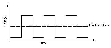
When the time that the voltage is high (the duty cycle) is half the total time in question, the effective voltage is about half the total voltage.
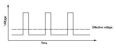
When the duty cycle is reduced to one quarter of the total time, the effective voltage is about one quarter of the total voltage.
As with direction, there are many controllers that will vary the speed of your motor, so if you don’t want to delve into the timing issues yourself, you can rely on products made for the job.