Basic Electrical Definitions
Electricity is the flow of electrical energy through some conductive material. Electronics refers to using changing electrical properties to convey information. Electronic sensors convert some other form of energy (light, heat, sound pressure, etc.) into electrical energy so that we can interpret what’s going on electronically. For example, a microphone changes sound pressure waves in the air to a changing electrical voltage. By amplifying and reading that electrical signal, we can interpret what the sound was that caused it. This process of changing one energy into another is called transduction, and devices that do it are called transducers. Much of the technical work of physical computing is about figuring out what form energy a person is putting out, and what kind of transducer you can buy or build to read that energy. In order to do that, though, it’s necessary to understand a few things about electricity. We’ll start with a few terms we’ll use to refer to electrical properties and components. After that, we’ll talk about the important relationships between some of these terms.
Current is a measure of the magnitude of the flow of electrons in a circuit. It is measured in Amperes, or Amps. Many people explain electrical flow by using water flow as an analogy. Following that analogy, current would be how much water (or electricity) is flowing past a certain point. The higher the amperage, the more water (or electricity) is flowing.
Voltage is a measure of the electrical energy of a circuit. It is measured in Volts. In the water analogy, voltage would be the water pressure. Think of a geyser as high voltage, and the shower of a low-rent apartment on the fifth floor of a tenement building as low voltage (unless you’re one of those lucky people with good water pressure!).
Resistance is a measure of a material’s ability to oppose the flow of electricity. It is measured in Ohms. A sponge in the pipe would act as a resistor, limiting the current (and the voltage) flowing through the pipe.
A circuit is a closed loop containing a source of electrical energy (like a battery) and a load (like a light bulb). Every circuit has to have a load of some sort, All of the electrical energy in a circuit has to get used by the load. The load will convert the electrical energy to some other form of energy. A circuit with no load is called a short circuit. In a short circuit, the power source feeds all of its power through the wires and back to itself, and either the wires melt (if you’re lucky), or the battery blows up, or something else disastrous happens.
Below is a very basic circuit, consisting of a lamp, a switch, and a battery. The electrical energy coming from the battery is converted to heat and light energy by the light bulb.
Components
Conductors are materials through which electrical current moves freely.
Insulators are materials which prevent the flow of electricity.
Resistors resist, but do not totally block, the flow of electricity. They are used to control the flow of current. Current can move either way through a resistor, so it doesn’t matter which way they’re connected in a circuit. They are symbolized like this:

Capacitors store up electricity while current is flowing into them, then release the energy when the incoming current is removed. Sometimes they are polarized, meaning current can only flow through them in a specific direction, and sometimes they are not. If a capacitor is polarized, it will be marked as such on the diagram. Don’t wire a polarized capacitor backwards; it might explode.
Capacitors are symbolized like this:
Diodes permit the flow of electricity in one direction, and block it in the other direction. Because of this, they can only be placed in a circuit in one direction. They are symbolized like this:

Light-Emitting Diodes (LED’s) are special types of diodes which emit light when current flows through them. They are symbolized like this:

There are many other types of components which you’ll come across:
- switches control the flow of current through a junction in a circuit:
- transistors and relays are switching devices:
- thermistors change resistance in reaction to varying temperature;
- photoresistors change resistance in reaction to varying light;
- flex sensors change resistance in reaction to being bent or flexed;
- piezoelectric devices create a varying voltage in reaction to slight changes in pressure.
Relationships
Voltage (V), Current (I), and Resistance are related (R) are all related, by the following formula:
Volts = Amps x Ohms, or
V = I x R
Current (I), voltage (V), and resistance (R) are also related to electrical power (P) (measured in watts), as follows: Watts = Volts x Amps or
W = V x A
Electrical current flows from places of higher potential energy to places of lower potential energy (i.e. from positive to negative).
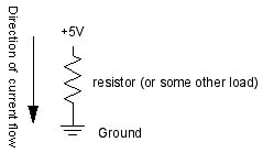
Ground is the place in a circuit with where the potential energy of the electrons is zero. Sometimes this point is connected to the actual ground, either through a grounded electrical circuit, water pipe, or some other method. Basically, any conductor that goes to the earth will do.
A few important rules:
Current follows the path of least resistance to the ground. So if it has a choice of two paths in a circuit, and one has less resistance, that’s the path it’ll take.
In any given circuit, the total voltage around the path of the circuit is zero. Each component that offers a resistance lowers the voltage, and by the time we reach the end of the circuit loop, there will be no voltage left.
The amount of current going into any point in a circuit is the same as the amount coming out of that point.
These last two rules give us a way to figure out what’s going on when we put components in a circuit. When we look at how components in a circuit are placed in relation to each other, there are two ways we can do it: one in line after another, or side by side. When they are one in line after another, we say the components are in series with one another. Side by side, they are in parallel with one another.
Let’s look at how the current and voltage changes when components are in series or in parallel:
When two components are in series, they are placed one after another, like so:
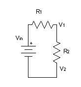
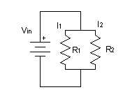
For resistors in parallel, the voltage across them is equal, but the current is divided between them. The total current is constant, however, so we know that the divided current across the parallel resistors is equal to the total current. So I1 + I2 = Itotal.
Though it’s sometimes useful to think about the mathematical relationships of parallel and series circuits, it’s often more useful to think about them in terms of practical effects. Again, think of the water metaphor. For the series example, if one resistor lowers the voltage (water pressure), only a smaller voltage (trickle of water) gets through to the next. For the parallel example, the amount of water from the main stream (total current) gets divided into two streams, but the total amount of water flowing through those two streams is equal to the original amount of water. Keeping in mind these basic relationships will help you figure out what the effect of one component is on another when you see them in a circuit together, even if you don’t know (or care about) their precise mathematical relationship.
When you’re ready to begin building circuits, read the notes on breadboards for a quick introduction to how to use a solderless breadboard.