This page covers only the details of MIDI communication on the PIC using PicBasic Pro.
Random Numbers and Physical Computing
Most microcontrollers don’t have a random function. Random functions are not truly random, they’re actually a complex mathematical formula that results in a number that “seems” random. That can take up lots of processing time, so it’s usually the first function to go when writing a microprocessor language.
In fact, most of what you do in programming physical computing projects is to figure out how to deal with the world’s natural randomness and make it look smooth. A photoresistor read through an analog-to-digital converter, for example, will never give you a nice steady number, it always fluctuates with tiny changes in lighting that your eye can’t see. Your consciousness is a great leveller for the sensors that are your eyes, ears, skin, nose, and taste buds When you move a photoresistor from one room to another, your readings will be totally different, and all of a sudden, you have to re-calculate what is “average” and what constitutes the lighting change that you want. And that’s just one of many examples. The fact is, data from sensors is filled with the noise of the real world. Plan for it in advance.
Technorati Tags: pcomp, physical computing, programming
Branch
BRANCH allows branching to one of multiple subroutines depending on the value of a specified variable. It’s the equivalent of a case statement. PicBasic Pro also has a BRANCH statement, as does mBasic. It looks like this:
BRANCH value, [label1, label2, label3...]
If value = 0, the program goes to label1. If value = 1, the program goes to label2. If value = 2, it goes to label3, and so forth.
Here’s a BS2 program illustrating BRANCH:
Sound in to a Microntroller
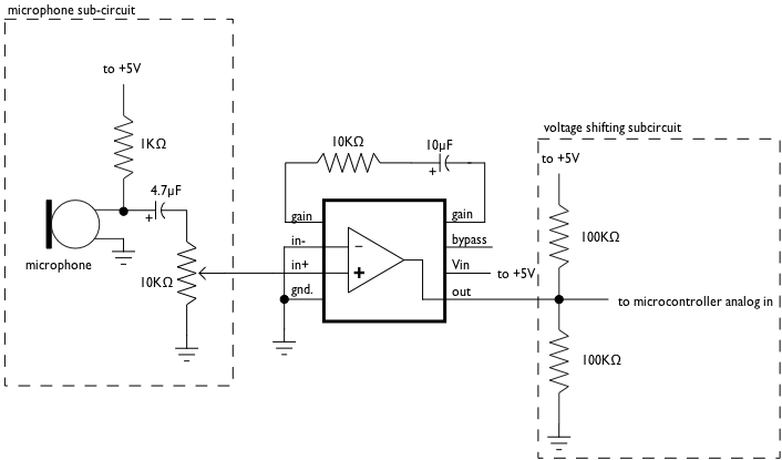
Microcontrollers can take sound in as an analog input, for crude measurements. While 8-bit ones (the Basic Stamp, BX-24, PIC, Arduino, etc) are not fast enough to read the frequency difference between various sounds, they can read sound levels. A line-level audio signal (which is what a typical CD or MP3 player produces) varies between -1V and 1V, a range of 2V total. If you raise that up so that it varies between, say, 3.5V and 1.5V, you can read it using the analog input on your microcontroller
First, if you have a microphone, you won’t be able to connect it directly. A microphone’s voltage, known as mic level voltage, is only a few millivolts at best. If you put it through a preamp such as a mixer board, or through an amplifier, you get a line level signal, which you can read.
A simple way to do this is to buy a preamplifier kit, something like the Velleman K1803 Universal Mono Preamplifier from Jameco (part no. 117612). For $8.95, it’ll save you some troubleshooting time, and cost about as much as the circuit below. Or you can build your own.
The following circuit uses a Condenser microphone element from Radio Shack (part no. 270-090C) and an amplifier chip also from Radio Shack (LM386 Audio Amplifier). The amplifier raises the microphone’s signal so it’s within line level tolerances, -1V to 1V. To raise that to a 1.5V to 3.5V range, we use a voltage divider (the two 100K resistors). Normally, the voltage between the resistors would be 2.5V (since their resistance is equal). When we add in the line level signal, we get 1.5V to 3.5V.
Note that the 10K variable pot is using all three pins of the potentiometer. The center pin goes to pin 2 of the amplifier, the end pins to the mic and pin 3, respectively. The variable resistor is your volume knob. I used an audio taper pot, since I wanted the curve of the pot to follow the sound’s volume.
Note that the capacitors are polarized electrolytic capacitors, so it matters which way they face.
In the BX-BASIC code, I found my base value (when all was silent) was about 512. So I subtracted that, took the absolute value of the result (so that negative numbers would always read as positive), and got a sound level varying between about 1 and 500. You may need to adjust these values depending on your setup.
dim soundIn as integer

Sub main()
    call delay(0.5)  ' start  program with a half-second delay

    do
        soundIn = abs(getADC(13)- 512)

        debug.print "soundIn = " ; cStr(soundIn)
    loop

End Sub
Here’s the same code in Wiring/Arduino:
void setup() {
	Serial.begin(9600);
}

void loop() {
	// read the audio in on analog 0:
	int soundLevel = analogRead(0) -512;
       Serial.print( "soundIn = ");
	Serial.println(soundLevel, DEC);
}
Serial Call-and-Response (Director/Lingo)
Here’s an example where a desktop computer running Director receives data from a BX-24. In this case, the BX-24 is sending 3 bytes, one for each of 3 analog sensors. the Director program checks to see how many bytes there are in the serial port buffer. If there are none, it asks for data. If there are five, it reads the data into five variables. It runs this checking routine repeatedly (in the exitframe or idle), so that if there are some bytes, but not a full three, it skips the whole routine and goes about its other business.
This example uses Geoff Smith’s SerialXtra version 1.0 for Director.
Continue reading “Serial Call-and-Response (Director/Lingo)”
Analog in using RCTIME
The RCTIME command is used to obtain a varying number from the charge or discharge of a capacitor in a resistor-capacitor circuit. The PWM command produces a modulated pulse on an oputput pin to simulate a varying voltage. The FREQOUT command pulses a frequency on the given pin.
Stepper Motor Control
This post has been moved to a permanent page on my site. You can find it at this link.
PicBasic Pro Debug Statement
The debug statement in picBasic Pro is a limited version of asynchronous serial communication. You have to define the debug port and pin, the baud rate, and the mode at the top of your program, and you can’t change any of these settings within the progam. Once that’s done, though, sending messages to the PC is a snap. Connect the whatever pin you use on te PIC to debug to the serial input of a PC (pin 2 on a DB-9 serial connector), and connect pin 5 of the DB-9 connector to ground. Then open HyperTerminal, set the baud rate to 9600, and run this program.
ADC In (Low Level Version)
The analog-to-digital converters on the 18Fxx2, 16F87x, and 16F81x series PICs (and others) are of 10-bit resolution. This means that when they measure an incoming voltage, they compare that voltage to a reference voltage, and give you the comparison represented as a 10-bit number (0-1023).
To use the analog-to-digital converters on a PIC through picBasic Pro without using ADCIN, you need to know something about the special memory registers on the PIC related to the ADC. The registers you need are as follows (for more on these registers, see the data sheet):
- ADCON0 – ADC configuration register 0
- ADCON1 – ADC configuration register 1
- TRISA/TRISE – input/output state register for port A (TRISE is for port E, on the 40-pin PICs only)
- ADRESH – ADC conversion result register, high byte
- ADRESL – ADC conversion result register, low byte
ADC In
This example reads an analog input on PORTA.0 and sends its value out serially on PORTC.6
Continue reading “ADC In”