It’s been a long time since my last post on this site. Time to update it a bit.
Introduction
Recently, some colleagues of mine and I were looking for a digital multimeter that could be used by people with low or no vision. We found a pretty good low-cost Bluetooth-connected meter from General Tools, model TS-04 (credit to Pedro G.C. Oliveira for finding it). It connects to an app for iOS or Android that’s reasonably accessible with a screen reader, but I thought it’d be helpful if it were possible to build customized interfaces for it, to match the user’s abilities and preferences more closely. What follows is an explanation of the process. The final code to make it possible can be found on my GitHub account.
If you’re new to Bluetooth LE, check out Alasdair Allan, Don Coleman, Sandeep Mistry’s book Make: Bluetooth (available in the Maker Shed), or this introduction that we did a few years ago on gitHub. To figure out the protocol, I used Punchthrough Design’s LightBlue app on the MacOS (available in the MacOS app store) to connect to the meter, a lot of experimentation in JavaScript, and the Mac calculator, in engineering mode so I could look at the bits (press command-3 in the calculator to enter engineering mode).
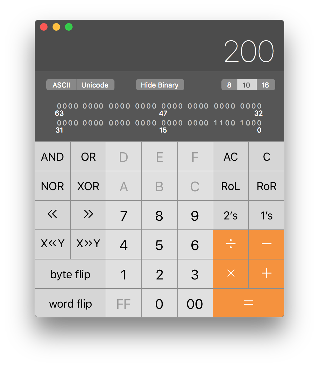
Apple calculator in engineering mode (press command-3 to enter this mode). In this mode, you can view numeric results in decimal, hexadecimal, or octal modes, you can see the binary values of each number, and you can perform bitwise operations like AND and OR on numbers.
Connecting to the Meter from JavaScript
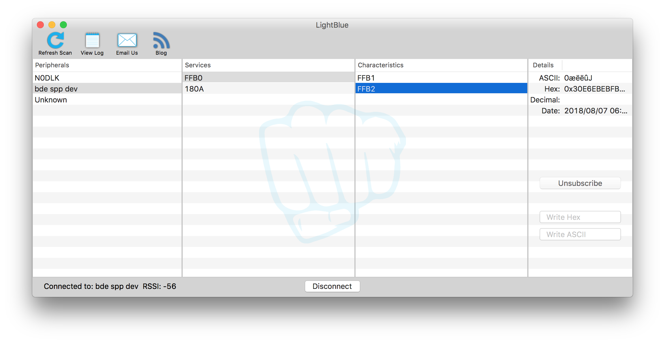
LightBlue is useful for learning the UUIDs of Bluetooth LE peripheral devices and their services and characteristics. Once I knew those, I could connect to it using a Bluetooth LE programming environment. I chose to use Web Bluetooth (details available here) to make it easy to build an interface in HTML that could be used in a browser. Yining Shi’s example for p5.js was useful (on gitHub), as was Uri Shaked’s post on Medium (at this link). My connection code is on my gitHub repository at this link.
It’s worth noting that web Bluetooth may not be the best solution to this problem. As of this writing, it only works in Chrome, and the device discovery chooser is not accessible to some screen readers, from what I can see. I don’t believe a solution is forthcoming to that problem until it’s available in other browsers. But hopefully it will change if web Bluetooth catches on in other contexts.
The meter’s primary service uses the UUID FFB0, and has two characteristics. The first, FFB1, continually sends the ASCII string SPP:sendData 08\s\n\ which is not so useful. The second, FFB2, sends a nine-byte string of binary data that appears to change as you change the meter’s settings. I converted it to a string of numbers it with the following JavaScript function:
function handleData(event) {
var buf = event.target.value.buffer;
if (buf.byteLength >= 20 ) {
// reading characteristic FFB1:
var str = String.fromCharCode.apply(null, new Uint8Array(buf));
console.log('I got ' + str);
} else {
// reading characteristic FFB2:
console.log(new Uint8Array(buf));
}
}
The Data
To figure out how the meter worked, I looked at the display and went through all the settings to understand what each one looked like.
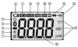
Next I made a JSON model of the meter’s relevant features like so:
var meter = {
value: '', // number value
negativePolarity: '', // DC negative polarity
units: '', // what you are measuring: V, A, ?, etc.
magnitude: '', // kilo-, milli-, mega-, micro- ,etc.
acDc: '', // AC or DC, for V and A readings
setting: null, // what setting (function) you're on
hold: null, // hold current reading onscreen
autoRange: null, // autoranging feature
ncv: false // non-contact AC voltage beep
}
That gave me a data structure I could fill in that could be used for any interface I want to build.
The first and last bytes of characteristic FFB20 don’t change; the first is always 48, the last is always 1. Here’s a typical string, showing what happens when the meter’s on the voltage setting, reading 000.0 mV DC:
[48, 226, 235, 235, 251, 11, 129, 66, 1]
The remaining seven bytes are 56 bits. The display has 53 discrete symbols on it: four seven-segment numerals, three decimal points, a negative sign, and 21 assorted other symbols. It seemed logical that the 56 bits would represent the 34 symbols on the meter, so I tried all the meter settings, examining the bits using the calculator to find out. Isolating the non-numeric functions was pretty straightforward. Here’s a breakdown of the symbols I worked out for the nine bytes:
Byte 0: unchanging, always 48
Byte 1:
- bit 4: negative sign
- bit 2: auto-ranging
- bit 0-1: DC/AC
- AC: 01
- DC: 10
Byte 2:
- bit 4: decimal point in second digit
Byte 3:
- bit 4: decimal point in second digit
Byte 4:
- bit 4: decimal point in second digit
Byte 5:
- bit 7: diode
- bit 6: k
- bit 4: µ
- bit 2: NCV beep signal (middle LCD of last digit)
Byte 6:
- bit 7: hold symbol
- bit 5: resistance symbol
- bit 3: continuity
- bit 2: M
- bit 0: m
Byte 7:
- bit 7: NCV symbol
- bit 6: always on; could be Bluetooth or Auto-off
- bits 4-5: Temperature:
- 01: F
- 10: C
- bit 3: low battery
- bits 0-1: Voltage, amperage
- 01: A
- 10: V
Byte 8: unchanging, always 1
With those values known, I could set the properties of my meter JSON object using some bit-masking to check to see which bits were set. For example, here’s the check for auto-ranging:
// byte 1 bit 2 is autoranging:
meter.autoRange = ((data[1] & 0b100) > 0);
The other bit checks are similar. The full program is in the ble-ts04.js file.
The Numerals
The numeric data was more of a mystery. The lower four bits of bytes 2 through 5 changed with the digits as follows:
- 0 = 1011
- 1 = 1010 same as 7
- 2 = 1101
- 3 = 1111 same as 8, 9
- 4 = 1110
- 5 = 0111 same as 6
- 6 = 0111 same as 5
- 7 = 1010 same as 1
- 8 = 1111 same as 3, 9
- 9 = 1111 same as 3, 8
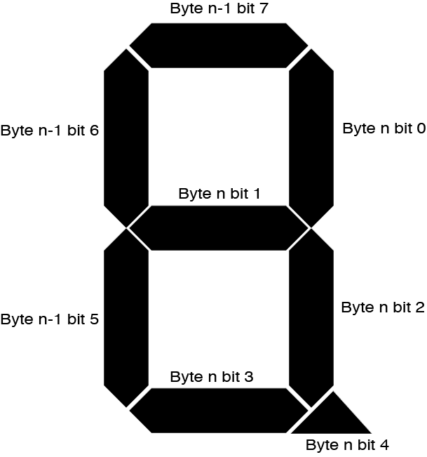
As noted above, bit 4 of bytes 1 through 4 are all associated with a decimal point for one of the digits, or the negative sign. The upper three bits of bytes 1 through 4 appeared to change with the digits, but the pattern doesn’t make obvious sense. They’re not binary representations of the numbers 0 through 9. But if you lay them out on a seven-segment LCD pattern, they begin to make sense. Figuring this out took some drawing of numbers, and guesswork. The digits with a common pattern – for example, 3, 8, and 9 – all have segments in common. That led me to look at the three changing bits in the previous bytes. Sure enough, those bits changed predictably with the digits as well. Starting with byte 1, each digit is made up of the high three bits of one byte, and the lower four bits of the next byte. Going clockwise from the upper left, the segments’ bits are as follows, for digit n:
- Left upper: byte n bit 0
- Center: byte n bit 1
- Left lower: byte n bit 2
- Bottom: byte n bit 3
- Decimal point: byte n bit 4
- Right lower: byte n-1 bit 5
- Right upper: byte n-1 bit 6
- Top: byte n-1 bit 7
The diagram below shows you the layout of which bits control to which segments:
With this knowledge, I could make a case statement that would extract the correct digit from the binary values. Here it is:
// parse the value of a digit from the bits in bytes 1-4
function makeDigit(byteValue, prevValue) {
let digit = '';
// combine the upper three bits of the first byte
// with the lower four bits of the second byte.
// bit 4 is always the decimal point, so it's ignored here:
let numberValue = (byteValue & 0b1111) | (prevValue & 0b11100000);
switch (numberValue) {
case 0:
digit = ' ';
break;
case 0b11101011:
digit = '0';
break;
case 0b1010:
digit = '1';
break;
case 0b10101101:
digit = '2';
break;
case 0b10001111:
digit = '3';
break;
case 0b01001110:
digit = '4';
break;
case 0b011000111:
digit = '5';
break;
case 0b11100111:
digit = '6';
break;
case 0b10001010:
digit = '7';
break;
case 0b11101111:
digit = '8';
break;
case 0b11001111:
digit = '9';
break;
case 0b01100001:
digit = 'L';
break;
case 0b11100101:
digit = 'E';
break;
case 0b11100100:
digit = 'F';
break;
}
return digit;
}
There are still some missing pieces. I didn’t try to find the battery, Bluetooth, or Auto-off icon bits, because they’re not useful in general operation. I couldn’t get data on the continuity beep, other than to look for 000.0 when in continuity mode. I didn’t try to remotely modify the display. This last may be possible since the characteristics are theoretically writeable without response.
The HTML Interface
I built a minimal HTML interface for the meter, just enough to show the pieces needed. A more fully-realized interface for different abilities would be a good idea. Mine is below. The elements should be self-evident. View the HTML here, or see the live preview here.
Finally, I wrote a pair of functions in a separate JavaScript document, display.js, to populate the page. I deliberately avoided any JS frameworks so you can pick your own when you make something with this. These two functions are called from the ble-ts04.js script when the meter gets new data (in handleData()) and when the meter disconnects (in disconnect()), respectively:
function fillDisplay(thisMeter) {
// Is the meter connected or not?
if (thisMeter.status !== null) {
document.getElementById('status').value = thisMeter.status;
} else {
document.getElementById('status').value = 'Connected';
}
// assemble the meter reading's value, units, and order of magnitude:
document.getElementById('value').value = thisMeter.negativePolarity
+ thisMeter.value;
document.getElementById('units').value = thisMeter.magnitude
+ thisMeter.units;
// IF measuring voltage or amperage, indicate AC/DC:
if (thisMeter.units === 'volts' || thisMeter.units === 'amps') {
document.getElementById('acDc').value = thisMeter.acDc;
} else {
document.getElementById('acDc').value = '';
}
// if measuring non-contact voltage, indicate that, and clear units:
if (thisMeter.ncv) {
document.getElementById('value').value = thisMeter.ncv;
document.getElementById('units').value = '';
}
// is auto-ranging on?
if (thisMeter.autoRange) {
document.getElementById('autoRange').value = 'AutoRange';
} else {
document.getElementById('autoRange').value = '';
}
// is the hold button on?
if (thisMeter.hold) {
document.getElementById('hold').value = 'hold';
} else {
document.getElementById('hold').value = '';
}
// what setting are you on?
document.getElementById('setting').value = thisMeter.setting;
}

// clear all the display elements except the connection status:
function clearDisplay(meter) {
document.getElementById('connected').value = 'Disconnected';
document.getElementById('value').value = '';
document.getElementById('units').value = '';
document.getElementById('acDc').value = '';
document.getElementById('autoRange').value = '';
document.getElementById('hold').value = '';
document.getElementById('setting').value = '';
}
The full project can be found on my gitHub repository. Enjoy, I hope it’s useful to someone.
Thanks to John Schimmel, Pedro G. C. Oliveira, Claire Kearney-Volpe, and Josh Miele and the Blind Arduino Blog for inspiration.